Expert engineers, advanced tools
SIMERA Technology Group (SIMERA) is a mechanical
engineering development company built around core capabilities of
advanced structural design and simulation services. Founded in 2010, the
company has 18 permanent employees representing more than 130 years of
engineering experience.
SIMERA’s clients include customers in government, research,
industrial equipment, and consumer product industry sectors. To excel in
these domains, SIMERA employs highly-skilled, experienced and
passionate engineers. Equally important, SIMERA uses advanced,
best-in-class engineering and product lifecycle management (PLM)
solutions to maintain a competitive edge.
PLM solutions from Siemens PLM Software help SIMERA’s engineers work
with precision, efficiency and creativity. From design through to
simulation and PLM, the cross-functional, comprehensive capability of
Siemens PLM Software tools make this possible. SIMERA appreciates the
collaboration and rapid design iteration capabilities of the solutions,
which aid the creative thinking of development teams.
The engineering and PLM solutions help orchestrate projects and track
changes in a completely traceable manner, giving design leads immediate
insight into the rationale and direction of design iterations.
A unified design and simulation solution
SIMERA formerly used different computer-aided design
(CAD) and finite element analysis (FEA) software tools. The tools in
themselves were productive, but SIMERA engineers had to transfer
information manually, handing data “over the wall” between the design
and simulation domains. The manual information handoffs were not
efficient and sometimes lead to versioning errors or simulation model
errors.
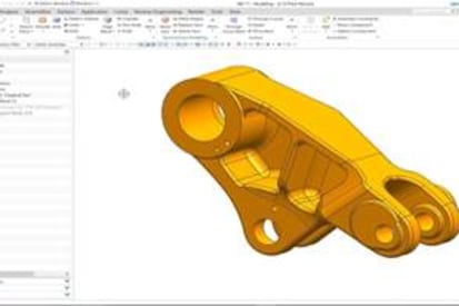
Implementing NX™
and Simcenter™ software was a natural step for SIMERA, as it provided a
unified CAD and simulation solution that better suited the company’s
quality, control and efficiency requirements. NX and Simcenter 3D, which
is also built on the NX platform, enable SIMERA to easily and quickly
move back and forth during the design and simulation cycle. Simulation
engineers can directly or collaboratively request model changes, and
validate those changes immediately. The added productivity of the
unified solution quickly justified the investment.
Improving control of the design processes
SIMERA also uses Teamcenter® software to improve
control over design processes. As is typical in small-to-medium
enterprises, SIMERA frequently relies on the expertise of key team
members to track and optimize requirements, link documents and manage
projects. This ad hoc approach has many limitations, especially in
projects involving extended resources, complex requirements and critical
non-compliance implications.
The company realized that PLM was essential for improving design
management, particularly in projects with an extended team of
stakeholders, larger design teams, complex requirements and strict
contractual obligations for execution. After an evaluation of available
PLM tools, SIMERA decided on Teamcenter because its capabilities spanned
a broad spectrum of the engineering processes. Other important criteria
included seamless integration with the NX CAD software and scalability
that would enable the system to grow with the company’s expansion. The
capabilities of Teamcenter for controlling product data with versioning
and traceability and for managing the design process were crucial in
fulfilling SIMERA’s requirements.
Excellent local support
The availability of local support for the solutions was also an important factor in SIMERA’s decision. The company relies on ESTEQ,
a Siemens PLM Software channel partner, for strategic consulting,
in-house training and system delivery, deployment and support. As the
largest provider of engineering simulation solutions in South Africa,
ESTEQ brought experience and expertise that were perfectly aligned with
SIMERA’s own core competencies. “Having excellent local support gives us
the confidence to tackle demanding tasks,” says Johann du Toit, chief
executive officer, SIMERA.
Pushing simulation to the limits
SIMERA engineers apply the unified NX and Simcenter
design and simulation solution to optimize the performance of precision
spaceborne imaging systems.
Satellite imagers have demanding requirements for controlling optical
surface deformations that could compromise image quality. Typically, a
10 micron rigid body movement of an optical surface can lead to an image
plane movement of 100 microns or more, and focus retention must be kept
within 20 microns or less. Likewise – but far more stringent –
deformations of optical surfaces themselves must be kept in check to a
tenth or more of the wavelength being reflected or refracted, which for
visible spectrum imagers starts at 450 nanometers. To put this in
perspective, a typical human hair thickness is about 200 times this
value. Clearly, error contributors should be fully understood and
analyzed to ensure successful operation. Furthermore, for flight
systems, structural components are usually made from carbon-fiber
reinforced polymer (CFRP) materials, whose behavior under fluctuating
thermal and moisture loss conditions are not always apparent due to
non-symmetric laminates and their geometries.
SIMERA’s challenge is to optimize component stiffness, thermal
expansion, and moisture expansion, taking into account the harsh
vibration of the launch, the vacuum and the constant thermal cycling of
the space environment. Simulating the component’s behavior requires a
multitude of scenarios involving multiple thermal and moisture-loss load
cases, as well as multiple options for the fiber directions in the
composite material layups.
The integrated design and simulation tools of NX and Simcenter 3D
help accelerate the extensive investigation. “Having an integrated
CAD-to-simulation environment greatly enhances the efficiency of design
iterations,” says Hennie Roodt, lead engineer at SIMERA. The system’s
ease of use was also beneficial to the engineers. “The Simcenter 3D
graphical user interface is intuitive and follows practical simulation
execution logic,” says Marius Cronje, lead engineer.
After many design and simulation cycles, SIMERA engineers were able
to optimize the design, improving the rigidity of the components while
minimizing the expansions due to temperature cycles and moisture losses.
SIMERA estimates that the all-inclusive tools of Simcenter make the
process three- to five-times more efficient. In practice, this means
that many more design options and scenarios can be investigated to
ensure optimal solutions. “Having the capability to quickly and
accurately investigate precise structural behavior, exposed to a
multitude of operational environments, greatly reduces our product
development risks,” adds Du Toit
Systems engineering with Teamcenter
The systems engineering capabilities of Teamcenter are
also crucial to SIMERA’s success with satellite imager projects. To
initiate projects, SIMERA engineers use Teamcenter to capture and
analyze the technical and performance requirements of the imaging system
as well as to define measurements and verification and validation
procedures.
The Teamcenter requirements management tools make the requirements
visible to everyone in the development team, which enables SIMERA to
allocate them to physical components and to continuously trace, verify
and maintain them. Requirements are also fully integrated with the
design tools of NX, so designers using NX could view requirements
information when creating or modifying component models. With NX
requirements validation tools, SIMERA engineers continuously check
designs for compliance.


 and displayed in a video viewer window.")


looslib (Mechanical)
If your company wants to seriously evaluate UG, contact them and they
may loan you a copy for 30-60 days.
“Wildfires are dangerous, hard to control, and economically catastrophic.”
Ben Loosli
CAD/CAM System Analyst
Ingersoll-Rand
Jason 123 (Mechanical)
for uses Solidworks, and it is sufficient for our needs. However, due
to company turmoil (layoffs, instability, no warm fuzzy anymore), I’ve
decided to look else for work. One highly regarded company in my area
uses UG and I want get some familarity to help get my foot in the door.
mjcole (Mechanical)
I’d try
to emphasize your previous experience with other software and ability to
learn quickly. Where I work now I got the position by convincing the
company that I’d be able to pick up UG quickly with my Pro/E and Catia
background.
It took me a few weeks to learn the basics and a few
months later I was modeling an Airfoil. UG can be frustrating at times
but after making some mistakes you’ll be able to avoid them in the
future. UG has a nice Training System called CAST Computer Assisted Self
Teach that can help you become comfortable with the software.
This
forum also has a lot of good postings and helpful engineers that can
help you find answers to common questions. I know it helped me out when I
first started learning UG.
Good Luck in your Job search.
Michael